Uniform Wall Thickness
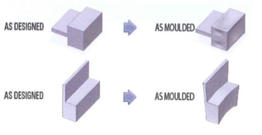
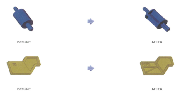
Good injection moulding part design relies on consistent wall thickness to minimise the potential for warped or distorted parts. As the plastic solidifies in the mould it freezes from the outside toward the inside. In thick sections, this results in inward pulling stresses due to contraction that can cause sink marks on the outer surfaces of the part or voids inside the wall.
In addition, because thinner sections will freeze faster than thicker sections there is also the possibility of stresses building up between thick & thin sections resulting in warpage.
The use of thinner, uniform wall thicknesses helps to avoid sinking.
A = Boss in corner causes sink.
B = Thinner walls on boss eliminate sink.
C = Thick walls cause sink, warp & excess shrink.
D = Thinner and uniform walls give accurate parts.
Warpage due to stresses in step transitions between wall thicknesses can be improved through the use of a ramp and gussets can be helpful to provide support in corners.

A = High stress concentrations.
B = Reduced stress concentrations.
C = Thinner walls result in uniform shrinkage during cooling.
D = Gussets provide additional support.
Thin ribs on thicker walls may provide stiffness but also can result in sinking on the outside of the wall. As a rule of thumb, the thickness of the rib should be about half of that of the wall to prevent this.
Uniform wall thickness during injection moulding can prevent errors that could result in a waste of time and resources. It’s important to ensure the wall thickness is uniform when injection moulding to promote better parts and more streamlined production. A roundup of issues that can occur as a result of varied wall thickness are:
- Warping – where twists and bends in a part’s shape occur from uneven shrinkage
- Sink marks – small craters occur when the molten plastic can’t cool completely
- Cooling rate issues – different wall thicknesses can cause different cool times
- Flow lines – lines or waves occur due to the different flow rates as the molten plastic fills the mould
- Short shots – where some section of the mould don't fill completely
- Gating challenges – gating systems ensure the smooth and even filling of the mould, uneven walls can cause the molten plastic to flow from thin to thick sections instead of thick to thin which causes the plastic to freeze in the thinner sections and block the flow
How to Prevent Issues with Non-Uniform Wall Thicknesses
It is important to determine the proper wall thickness for the part before attempting to keep all of the part’s walls as even as possible. The wall thickness should be enough to support the intended load of a part without compromising production.
- General wall thickness will be in the range of 0.5mm to 4mm, however, there may be some variations depending on the materials
- Wall thickness should stay below 5mm as thicker walls can lengthen the production cycle and be detrimental to the aesthetics
- Adjacent walls shouldn’t be any more than 40%-60% the thickness of each other
Coring Out
Plastic moulded parts which are too thick or have thick sections can be subject to excess shrink, sink, internal bubbles, voids, and poor cosmetics. This is due to the fact that plastic shrinks as it cools from the molten injected state to solid room temperature parts.
Coring out is a technique where the material is removed from a part leaving distinct walls and ribs which provide enough strength and mating surfaces for other parts in the assembly. Coring out is necessary to make the part mouldable and saves cost and weight. The key points are leaving ribs in the right location, correct sizing to maintain strength and retaining features that interface with others.

Benefits of Coring Out
Removing the excess material from the moulded part can help achieve a more uniform wall thickness. Coring reduces the wall thickness which therefore avoids sink marks which can improve its look and performance without influencing other important dimensions. Benefits of coring include:
- A reduction in wall thickness can reduce the risk of sinking, warping and flow lines
- Reduced manufacturing costs through less material weight
- Improved uniformity and performance
Surface Finish
The surface finish on a plastic part can serve many functions such as improving grip, hiding fingerprints, and facilitating paint adhesion. Many designers would also agree that a product's aesthetic appeal relies heavily on how a product looks and how it feels in the consumer’s hands.
Textures and lettering can be moulded on the surfaces as an aesthetic aid or for incorporating identifying information for end users. Texturing also helps hide surface defects such as knit lines and other surface imperfections. The depth of texture or letters is somewhat limited and an extra draft needs to be incorporated to allow for the withdrawal of the part from the mould without damaging the surface.
Benefits of Injection Moulding Surface Finishes
Surface finishes are critical to the success of a plastic injection moulding design. It can be used for aesthetic or practical purposes during injection moulding and come with a range of benefits and uses.
- Increases aesthetics – surface finishes on injection mouldings are used to improve the appearance and give the part a quality finish
- Covers marks – finishes can help to disguise process flaws generated by injection moulding such as tool machine marks, sink marks, weld lines and flow lines
- Improves functionality – the design of the part may need surface texture to improve grip quality
- Paint adhesion – adding surface finishes when injection moulding can help paint adhere firmly to the part
Draft for texturing is somewhat dependent on the mould design and the specific texture requirement. As a general guideline, 1.5 degrees minimum per 0.025mm depth of texture (a standard fine spark) needs to be allowed for in addition to the normal draft. More draft may be needed for heavier textures such as leather grain with a depth of 0.125mm that requires a minimum angle of 7.5 degrees.
There is usually a higher cost associated with aesthetic mirror-type finished surfaces as these require greater labour input with regard to the polishing of the mould.
No Draft Angle – Incorrect
Draft Angle – Correct


